Underwater drilling and blasting operation improvement strategies and technical methods
Several theoretical and technical measures to improve underwater drilling and blasting
1 Introduction
It is well known that underwater drilling and blasting projects are more difficult to construct because there is a water layer below the water surface during construction, which makes it impossible to directly observe the rock surface texture, karst cracks and other structural conditions and blasting effects. The adverse flow state of rapids, cross currents and vortices in the water area, as well as the silt and gravel covering the rock surface, make the underwater drilling and blasting excavation project more difficult.
The blasting of explosives is a high-speed chemical reaction phenomenon. The detonation speed of general civilian explosives can reach 3500~5000m/s, accompanied by the generation of major stresses such as air shock waves, water shock waves and seismic waves. These stresses may threaten and damage the safety of people, animals, ships and buildings near the explosion point, which must be given sufficient attention.
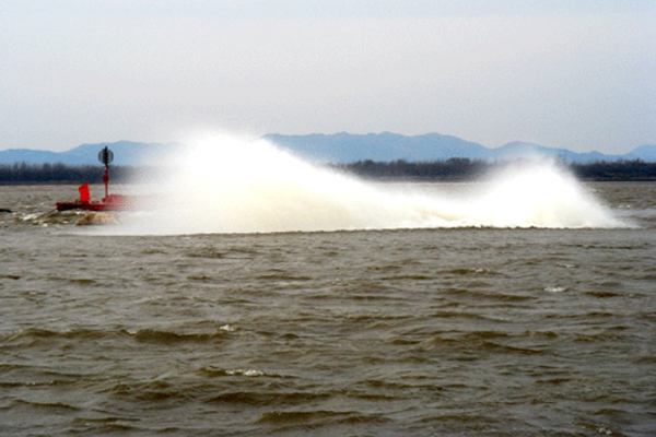
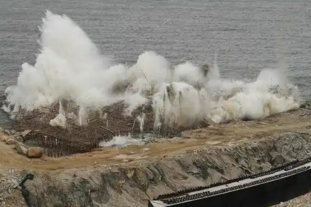
There are two main characteristics of explosives when they explode in the medium (rock). The first is that when the explosives explode in the rock of the drill hole, they produce high temperature, high pressure, and high-speed explosive force that is ejected in the direction of the minimum resistance line of the explosion point. This characteristic is the main theoretical basis for calculating the amount of explosives and directional blasting; the second is that after the explosives explode inside the rock, they produce compression crushing circles, throwing crushing circles, loosening damage circles, and cracking vibration circles from the inside to the outside. This is the theoretical basis for calculating the amount of explosives used in the blastholes, the spacing of the blastholes, and the spacing of the rows.
2 Correct selection of several parameters related to the calculation of the amount of explosives in the blastholes in underwater drilling and reef blasting projects
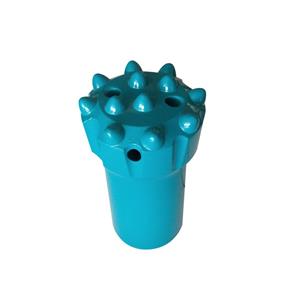
Since the 1970s, my country has introduced down-the-hole drilling rigs from abroad for underwater drilling and reef blasting. Since the impactor (impact hammer and drill bit combination) of the down-the-hole drilling rig has always been placed on the surface and inside the rock, the loss of impact energy is very small and the impact drilling effect is very high. Therefore, underwater drilling and blasting has become the most important and most efficient construction method for underwater reef blasting projects in waterways.
In the Technical Specifications for Water Transport Engineering, the calculation formula for the charge of blastholes is:
The charge of the first row of blastholes Q=0.9baH.
The charge of the rear row of blastholes Q=q.baH.
In the above formula:
Q----blasthole charge (kg);
a----blasthole spacing (m);
b----blasthole row spacing (m);
H. ----Designed excavation rock layer thickness, including the thickness of the calculated super-deep value (m);
q. ----Underwater reef blasting unit explosive consumption (kg/m3), which is an empirical value, please refer to Table 2.3.2 of the Technical Specifications for Water Transport Engineering for selection.
The calculation formula for the charge of the blasthole mentioned above is mainly determined by the product of the amount of crushed stone after blasting, including the calculation of the super-deep crushed stone, the unit explosive consumption of stone, and the empirical coefficient. The calculation formula is simple and clear, but in order to make the charge of the blasthole conform to the actual situation, and avoid the residual stone and stone ridge in the blasting area due to the charge of the blasthole, the excessive coarseness of the stone after blasting, which affects the efficiency of excavation and slag removal, or the excessive crushing of the stone, which increases the cost of explosive consumption, the following relevant parameters must be correctly selected.
2.1 Blasthole length L. Parameters
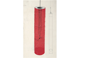
In the "Specifications", the bottom elevation of underwater boreholes should be the same as the bottom elevation of the same row of holes, and the charge length should be 2/3~4/5 of the hole depth. The smaller value is used for soft rocks and the larger value is used for hard rocks. The key issue here is whether the calculated charge of the blasthole meets the parameter requirement that the charge length is 2/3~4/5 of the blasthole depth. In the construction practice of underwater reef blasting, the charge length of the blasthole is often greater than the requirement of 2/3~4/5 of the depth of the blasthole because the blasthole diameter is too small or the ratio of the line-loaded explosive diameter to the blasthole diameter is less than 0.80. That is, after the blasthole is charged, the blasthole has no sufficient space for the plugging length, and even the depth of the blasthole cannot accommodate the calculated charge. When the length of the blasthole charge is too long, there will often be residual stone and stone ridges in the blasting area, resulting in incomplete blasting. To change and overcome the above problems, the main measures are to appropriately increase the diameter of the blasthole or improve the quality of the blasthole charge roll packaging, appropriately reduce the thickness of the bamboo tied outside the roll, or use hard plastic tubes as the roll packaging to effectively increase the diameter of the charge package, and use the diameter of the charge package ≥ 0.8 of the blasthole diameter.
2.2 Parameters of blasthole overdrilling depth h
The blasthole overdrilling depth refers to the overdrilling depth value below the thickness of the designed excavated rock, including the calculated over-depth value (0.2m for land drilling and 0.4m for underwater drilling). It is determined by forming the design blasting funnel size based on the empirical coefficient of the blasthole diameter, spacing, row spacing and blasthole charge. The overdrilling depth value h of the "Specification" is selected as a parameter of 1.0~1.5m. This parameter has both theoretical basis and empirical factors, but in construction practice, when the blasthole charge length L appears. When the value is greater than 2/3~4/5 of the borehole diameter, the blasting effect is generally poor. To solve this contradiction, there have been attempts to increase the over-drilling depth to 2.0~2.2, or even to 3~4m, so that the borehole charge blindly increases the over-drilling depth. Practice has shown that not only the bottom rock is too crushed, but the surface rock blocks are too large, making excavation and slag removal difficult, and even often requiring secondary blasting, which leads to a significant increase in the unit explosive consumption and engineering cost of underwater reef blasting.
2.3 Adjustment of unit explosive consumption and parameters such as blasthole spacing and row spacing for underwater reef blasting
Due to the complex geological and topographic factors such as the hardness, stratification, texture, cracks in molten rock, water depth, etc. of underwater rocks, the most reliable and fundamental measure to achieve high benefits in underwater reef blasting projects is: before large-scale blasting and excavation construction or in the early stage of construction, conduct drilling and blasting and excavation and slag removal tests on a small area (100-600 square meters) of stone layers to timely check the actual effect after blasting. If there are unfavorable conditions such as excessive coarseness of stone slag after blasting, low efficiency of machine excavation and slag removal, incomplete blasting of residual stone slabs and stone ridges, excessive crushing of stone slag after blasting, and excessive unit explosive consumption, the spacing, row spacing, overdrilling depth and unit explosive consumption of blastholes should be appropriately adjusted according to the actual situation until good post-blasting benefits are achieved.
3 Several technical measures to improve the actual effect of underwater reef blasting
3.1 Drilling positioning
In the designed channel for underwater reef blasting, accurately arranging the position of each blast hole is a basic measure to prevent missed or repeated blasting. According to experience, it is best to use a 1/100~1/300 scale channel topographic map and a total station to locate and arrange the drilling. It is not appropriate to use a level or directly use a tape measure to measure the distance method to locate and arrange, so as to ensure that the position of the blast hole is ≤0.2m away from the design position. If the actual location of the blast hole is a bad geological condition such as a karst gully and drilling is impossible, drilling should also be done at an appropriate location near the planned drilling location.
3.2 Measures to minimize the number of blasting times
In large-scale drilling and blasting projects, the cracks in the boundary rock blasting after each drilling and blasting will affect the next normal drilling efficiency and slag removal efficiency to varying degrees. For example, in the drilling and blasting of two pier foundation stones of several tens of square meters each at a certain dock, the drilling and excavation efficiency was extremely low due to the improper measures of drilling 1~2 holes each time for multiple layered blasting in a small area, and the construction period and cost were more than 2 times higher than planned. Therefore, increasing the measures of loading and wiring blasting and minimizing the number of blasting large-scale blasting are effective measures to improve work efficiency.
3.3 Measures to improve the accuracy rate of large-scale blasting
3.3.1 In order to prevent the occurrence of blind blasting of blasthole packages due to problems with the quantitative detonation of detonators and line connections, in addition to strictly checking the quantitative detonation of detonators and power transmission lines before blasting, practice has proved that the interval between the charge packs of each blasthole is loaded with at least two detonating detonating cords, which is one of the effective measures to improve the accuracy rate of underwater reef blasting.
3.3.2 Before each blasting of a large area and multiple boreholes, a blasting network design must be done. In the network design, the materials of the borehole detonating detonators and wires, the line connection method, and the waterproof performance of the explosive package must be considered. A blasting simulation test must be carried out to optimize the network design in a timely manner. At present, when detonating a network of multiple boreholes, multiple plastic detonating cords are generally connected in parallel and then grouped with 8# electric detonators or percussion to detonate. Since multiple plastic detonating cords are connected in parallel, the reliability of detonating with electric detonators is difficult to ensure that all of them are accurately detonated, in order to improve the accuracy rate, the number of electric detonators can be increased or small explosive packages can be added for detonation. In addition, the most important blasting network directly uses detonating cords and other measures such as parallel or series connection with multiple groups of boreholes for percussion detonation.
3.3.3 On the water surface of the blasting area with complex flow patterns, place the blasting network line on the water surface of several buoys to facilitate network connection and inspection, and prevent the rapid current from causing the wire to disconnect and refuse to explode.
3.4 Measures for using micro-difference blasting technology
The micro-difference blasting technology with millisecond delay for blasthole charging not only reduces the amount of explosives in the largest section (shot) as much as possible to effectively reduce the threat of seismic waves and water shock to the safety of nearby buildings and ships, but also, when micro-difference delay blasting is carried out in each multi-hole large area, the seismic waves generated by the blasting of each blasthole are staggered to reduce the superposition of seismic stress, which is conducive to rock crushing and improving the efficiency of mechanical slag removal.
4 Conclusion
Underwater reef blasting is a special water transport project with huge engineering. During construction, strict and accurate implementation of the "Technical Specifications for Water Transport Engineering" is an important guarantee for obtaining high-quality and efficient project engineering. In the specific application of the various calculation parameters and technical measures in the "Specifications", small-scale tests before construction, or in construction practice, continuous summary and correction according to different conditions such as engineering geology and water patterns at each site, can obtain truly valuable parameters and technical measures.
