Common Failure Modes of PDC Drill Bits and Cause Analysis
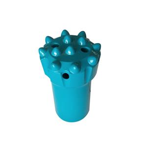
Overview A mining PDC (polycrystalline diamond compact) drill bit consists of the bit body, PDC cutting cutters, and gauge-protecting carbide. Both the PDC cutters and the gauge-protecting carbide are brazed to the bit body. During drilling, torque and downforce are transmitted from the rig through the drill string to the bit; rock fragmentation is performed by the PDC cutters while the gauge-protecting carbide shields the bit body around its circumference to slow wear. Because the stress state at the bit face is highly complex, multiple factors — formation conditions, drilling procedure and equipment selection, operator skill, and quality control of the bit itself — can affect performance and produce various failure modes. Based on field surveys and systematic analysis of failed bits, the following summarizes the main failure types and their causes.

I. Failures of PDC Cutters PDC cutters are the core rock-fragmenting elements of the bit and can fail in several ways:
Normal wear Normal wear is the expected material loss from prolonged rock cutting. It appears as gradual abrasive wear of the diamond table and the cemented-carbide substrate. The worn surface is smooth without obvious fracturing or spalling and is considered acceptable end-of-life wear.
Cutter loss (full detachment) Cutter loss refers to a cutter completely separating from the bit body, leaving the brazing pocket empty and causing bit failure.
Main causes
Thermal damage at the bit face (burning): Dry drilling or blocked bit water passages prevent adequate cooling during high-speed cutting, rapidly raising temperatures at the bit face. If the temperature exceeds the brazing filler’s melting or degradation threshold, the braze joint fails and the cutter falls out.
Inadequate brazing process control: Poor pre-cleaning, cold or porous braze joints, improper degassing, or insufficient post-braze heat treatment/soak time can all reduce joint strength and lead to cutter detachment.
Countermeasures
Production side: enforce strict process control for brazing — ensure clean surfaces, proper braze fillets, and consistent post-braze heat treatment to produce robust joints.
Field side: adopt wet drilling with clean water and avoid dry drilling; before running long holes or adding drill pipe, confirm return flow at the collar and verify bit water passages are unobstructed to prevent cooling loss.
Chipping / fracture of the diamond table Chipping is a high-frequency failure in which the diamond table flakes or fractures; in severe cases the diamond table and carbide substrate break away together, causing immediate loss of cutting ability.
Main causes
Insufficient cutter toughness or bonding: cutters with low impact resistance or weak bonding between the diamond table and carbide substrate are prone to chipping under shock loads.
Improper drilling parameters: excessive feed/downforce causes cutters to experience loads beyond their strength limits.
Harsh formation conditions: very hard, highly fragmented formations impose high impact loads that exceed cutter impact toughness.
Inappropriate bit design: failing to follow the principle “harder formation → larger cutting/rake angle” can leave cutters with too aggressive geometry for hard formations, increasing stress and promoting chipping.
External obstructions: encountering anchors, rock bolts, or reinforcement in the hole can produce sudden shocks that chip cutters.
Countermeasures
Follow manufacturer recommendations for operating parameters and set feed and rotation to match formation hardness.
Select cutters and bit geometry matched to formation: increase cutting/rake angle in harder formations to reduce attack aggressiveness and lower impact loads.
Use cutters with higher impact toughness or modify the external shape of the diamond table (e.g., convex/curved profiles often offer better impact resistance than flat tables under comparable manufacturing conditions).
Plan hole trajectories to avoid known obstacles like rock bolts or anchors.
Delamination between diamond table and substrate Delamination is separation of the diamond table from the cemented-carbide substrate, leading to loss of cutter integrity.
Main causes
Large residual interfacial stresses and mismatch in coefficients of thermal expansion between the diamond table and the carbide substrate. Heat generated by cutting and rapid cooling from flush fluid produce thermal stresses; combined with residual stresses from manufacturing and applied impact loads, these can cause the diamond table to peel away.
Countermeasures
In manufacturing, choose compatible bonding/braze materials and process parameters to minimize residual stresses. Optimize sintering/brazing procedures to relieve or compensate interfacial stress.
Improve mechanical interlock by redesigning the substrate interface geometry (e.g., stepped or keyed interfaces) to enhance bonding strength and structural stability.
II. Bit-Body Failures Bit-body failures are typically manifested as blade (gauge wing) fractures. These failures occur mainly in matrix (sintered) bit bodies; steel-bodied bits, owing to higher material toughness, are less prone to blade breakage.
Main causes
Improper make-up/demake practices: matrix crown bits are often formed by powder metallurgy in a single sintering step. Although wear-resistant, matrix materials are less ductile. Striking blades during bit make-up or removal (for example, hammering on blades) can easily fracture the wings.
Poor sintering control: incomplete sintering or “cold” spots where metal powder did not fully consolidate produce weak zones or inclusions in the matrix, reducing structural strength and making blade fracture likely during use.
Countermeasures
Operational: standardize make-up and removal procedures. Use proper tools (spanners, lifting tongs, or extraction devices) to handle bits and avoid striking blades directly.
Production quality: enforce strict sintering process control and perform regular testing of metal powder feedstock to ensure powder quality and complete consolidation, preventing unsintered inclusions and weak zones.
Closing remark Effective prevention and mitigation of PDC bit failures require coordinated control across design, manufacturing, drilling parameters, and on-site operations. Matching bit design and cutter selection to formation conditions, maintaining rigorous brazing and sintering quality control, ensuring proper cooling and flushing during drilling, and following standardized handling procedures will significantly reduce failure rates and extend bit life.