Cross Bit Failure Modes and How to Extend Service Life in Rock Drilling
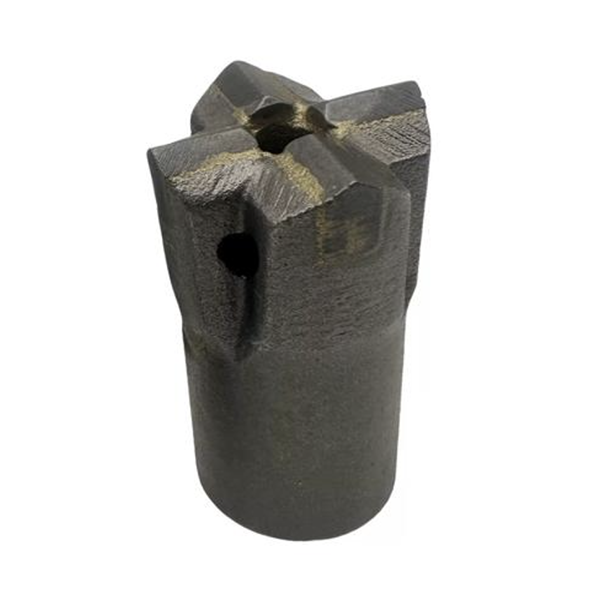
Cross bits remain widely used in coal mining, tunneling, quarrying, and general rock drilling. Their simple geometry, strong cutting structure, and practical performance make them suitable for many low- to medium-power drilling applications. However, a cross bit is also a consumable tool that operates under repeated impact, rotation, abrasion, and heat.
When a cross bit fails early, the cost is not limited to replacing the bit. Premature failure can reduce penetration rate, interrupt drilling, damage the drill steel, block flushing holes, create poor-quality holes, and increase labor time. In difficult cases, a broken component may require recovery work or result in an abandoned hole.
Most cross bit failures are related to one or more of four areas: bit design, material quality, manufacturing process, and field operation. Understanding the typical failure modes helps operators and drilling-tool buyers make better choices and improve tool life.
1. Bit Skirt Expansion and Cracking
One common failure is skirt expansion, often followed by cracking. The skirt is the lower body section of the cross bit that connects the bit to the drill steel. It must remain dimensionally stable while transferring impact energy and maintaining a secure connection.
When the skirt expands, the internal taper or connection area can become loose. The bit may gradually move deeper onto the drill steel, while the shank can create a step or wear point at the bottom of the skirt. This can lead to loose connections, blocked flushing holes, broken fragments, shank breakage, and premature bit failure.
Skirt expansion can occur when the bit body lacks sufficient structural strength for the applied load. If the skirt wall is too thin, the taper-hole angle is unsuitable, or the insert depth is insufficient, the bit body may not provide enough support.
Material properties also matter. A bit body that is too hard may become brittle and crack under impact. A body that is too soft may deform or expand more easily. The correct heat-treatment condition must balance toughness, hardness, and resistance to deformation.
Operational practices can make the problem worse. Poor fit between the shank and taper hole, incorrect bit installation or removal, excessive hammering, and improper regrinding can all damage the connection area. Operators should inspect the mating surfaces regularly and avoid using damaged drill steel with a new bit.
2. Fatigue Fracture of the Bit Body
Fatigue fracture is another major failure mode. It is often found in the “waist” area of the bit body, near the transition between the shank section and the lower part of the bit skirt.
This location can have a relatively small cross-section and may experience stress concentration during repeated impact cycles. Every blow from the rock drill creates a load cycle. Over thousands of cycles, even a small geometric defect or surface flaw can become the starting point for a fatigue crack.
The source article notes that a large share of bit-body fractures occur in this transition area. This highlights the importance of smooth structural design and careful manufacturing.
Several factors can increase the risk of fatigue fracture:
Insufficient skirt-wall thickness
Sharp transitions between internal and external surfaces
Small fillet radii or sharp corners
Inadequate material strength or toughness
Uneven heat treatment
Rough machining marks and surface defects
Lack of surface strengthening or corrosion protection
Poor contact between the shank and bit connection
Eccentric impact during drilling
Improper removal methods, such as striking the bit with a hand hammer
Good bit design should avoid abrupt changes in section thickness. Smooth radii and balanced geometry help reduce stress concentration. During manufacturing, machining marks should be controlled, and heat treatment should produce consistent properties throughout critical zones.
In field use, operators should avoid forcing a worn bit to continue drilling after excessive vibration or abnormal impact is observed. A small crack can grow quickly under repeated loading.
3. Insert Loss and Blade Separation
Cross bits commonly use hard alloy inserts or carbide cutting elements. If these inserts loosen, crack, or fall out, drilling performance can decline rapidly.
Insert loss is usually linked to poor brazing or bonding quality. The steel body, carbide insert, filler material, and joint design must work together. If the brazing process is not controlled properly, the joint may lack sufficient strength to survive repeated impact and thermal cycling.
The geometry of the insert pocket is also important. The pocket must support the carbide properly while allowing correct braze thickness and material flow. If the insert is not seated correctly, contact may be uneven and the load may concentrate on a small area.
Potential causes of insert loss include:
Incorrect brazing temperature or time
Incompatible braze alloy
Surface contamination before brazing
Incorrect insert-pocket geometry
Poor insert positioning
Excessive impact loading
Dry drilling and overheating
Severe vibration from poor drilling alignment
Manufacturers should use controlled brazing procedures and inspect the quality of insert installation. Operators should ensure that flushing is effective and stop drilling if an insert becomes loose or damaged.
4. Early Carbide Fracture
Carbide inserts are extremely hard and wear resistant, but they are not immune to damage. Early carbide failure can appear as edge chipping, corner breakage, cracking, fractured inserts, or complete insert loss.
The cause may be related to bit design, carbide grade, manufacturing quality, drilling conditions, or operator behavior. A carbide insert must have enough support from the steel body and must be matched to the rock condition. A carbide grade suitable for abrasive, hard rock may behave differently from one used in softer or highly fractured formations.
Improper drilling practices are often a major contributor to early carbide failure. Common examples include dry drilling, excessive heating, striking the bottom of the hole without effective penetration, over-sharpening the cutting edge, and running the bit in a damaged or uneven hole.
Dry drilling is particularly harmful because it reduces cooling and cuttings removal. Heat can build up rapidly, weakening the braze joint and increasing thermal stress in the carbide. Poor flushing also allows cuttings to be re-crushed, increasing wear and vibration.
Regrinding is another important factor. A worn cross bit should be sharpened before the carbide becomes severely damaged. However, over-grinding can create an excessively sharp, weak edge that chips quickly. Regrinding should restore the intended cutting geometry rather than simply remove material.
Preventive Measures for Longer Cross Bit Life
A longer-lasting cross bit begins with correct selection. The bit design, carbide grade, steel body, taper system, and flushing arrangement should match the rock hardness, abrasiveness, drilling equipment, and hole size.
Operators should also follow a preventive maintenance routine:
Check bit and shank fit before drilling
Inspect carbide inserts for cracks, looseness, and excessive wear
Maintain effective air or water flushing
Avoid dry drilling where flushing is required
Use correct impact, rotation, and feed settings
Regrind worn cutting edges before serious carbide damage occurs
Do not strike the bit during installation or removal
Replace damaged drill steel, worn shanks, and distorted rods promptly
Record abnormal failure patterns and review drilling conditions
Conclusion
Cross bit failure is rarely caused by one factor alone. Skirt expansion, body fatigue fracture, insert loss, and carbide breakage can result from a combination of design limitations, material properties, manufacturing variation, and incorrect use.
For drilling contractors, the most effective strategy is to choose a well-made cross bit, match it to the drilling conditions, and operate it with correct flushing and maintenance practices. This approach can improve penetration consistency, reduce unexpected downtime, and lower the total cost per meter drilled.