Electro-Hydraulic Drill Rig Troubleshooting: When a Hydraulic System Fails After Changing Power Sources
Electro-Hydraulic Drill Rig Troubleshooting: When a Hydraulic System Fails After Changing Power Sources
A drill rig can appear to have a hydraulic fault when the real cause is in the electrical system. This is especially true for electro-hydraulic rigs that use more than one power source, such as an electric motor for normal operation and a diesel engine for mobile or backup operation.
When a rig operates correctly with electrical power but fails to build hydraulic working pressure with a diesel engine, technicians may naturally suspect the diesel-driven hydraulic pump. However, a structured diagnostic process is essential. The failure may involve pressure regulation, pump condition, a control valve, a power supply circuit, or a protective fuse.
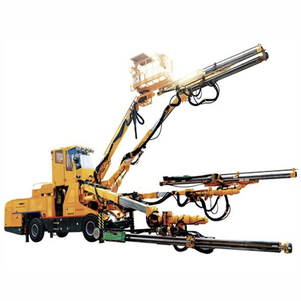
This article explains a practical approach to electro-hydraulic drill rig troubleshooting based on a case involving a Boomer282-type fully hydraulic drill rig. The key lesson is simple: hydraulic and electrical systems must be diagnosed as one integrated control system.
Start With the Failure Symptoms
In the reported case, the drill rig had worked normally for more than six months. When connected to a 380 V power supply, the rig operated normally. However, the battery charging indicator showed an abnormal condition during charging. When the diesel engine was used as the power source, the hydraulic system would not operate.
These symptoms suggested two possible fault areas:
A hydraulic system failure
An electrical circuit failure
The first step was to avoid assuming that the diesel-driven hydraulic pump was defective. Because the rig used two different power sources, comparing its behavior under each source provided important diagnostic evidence.
Check Common Hydraulic Fault Causes
When a hydraulic drill rig failure occurs, several common causes should be considered:
Working pressure set too low
Pressure-regulating valve spring weakened or broken
Serious external oil leakage
Internal leakage in hydraulic cylinders
Excessive leakage in directional control valves
Internal leakage caused by pump gear or end-cover wear
In this case, the system had already operated normally for months. That made an incorrect original pressure setting unlikely. External hose leakage was also ruled out through inspection.
The machine had two independent hydraulic pumps: one driven by an electric motor and one driven by a diesel engine. However, other hydraulic components, including hydraulic cylinders and directional control valves, were shared by both power systems.
Since the rig worked normally with the electric motor, technicians could reasonably conclude that the shared hydraulic cylinders and directional valves were not the main cause. This narrowed the investigation to the diesel-driven pump or the control system associated with diesel operation.
Inspect the Hydraulic Pump Carefully
The diesel-driven hydraulic pump was tested with a pressure gauge. Its output pressure was found to be normal. The pump was then disassembled and inspected. Gear clearance and end-face clearance were measured and found to be slightly large but still within the allowable range.
The pump end cover was ground to bring the clearance back toward the standard condition. After reassembly, the fault remained.
This is an important hydraulic pump fault diagnosis lesson. A component may show some wear without being the root cause of the current failure. Replacing or repairing a part simply because it looks worn can waste time and resources. Technicians should verify whether each suspected defect actually explains the complete symptom pattern.
Examine the Electrical System
The abnormal battery charging indication provided a critical clue. The drill rig used electro-hydraulic control, and a delayed solenoid valve identified as Y172 was powered by the battery or by the battery-charging circuit.
The charging circuit included a 16 A fuse. When technicians inspected the fuse, they found that it had blown. After replacing the fuse, the drill rig was tested again and the fault was eliminated.
At first glance, a blown fuse in the charging circuit may seem unrelated to a hydraulic system that will not operate with diesel power. The connection becomes clear when the delayed solenoid valve is understood.
The Role of the Delayed Solenoid Valve
The Y172 valve was designed to provide delayed no-load starting for the hydraulic system. When the diesel engine or electric motor first starts, the valve remains in its initial position. In this condition, hydraulic oil returns directly to the tank through an unloading path. The hydraulic pump starts with minimal load, making it easier for the engine or motor to start.
After approximately three seconds of energization, the delayed solenoid valve shifts. This closes the unloading circuit and allows the hydraulic system to enter normal working mode. The variable pump can then supply pressure and flow according to external load requirements.
If the solenoid valve does not receive electrical power, it remains in the unloading position. The pump may still rotate and produce oil flow, but the system cannot build the pressure needed for normal drilling functions.
In the reported case, the blown 16 A fuse prevented the battery from supplying power to the Y172 delayed solenoid valve during diesel operation. As a result, the hydraulic system remained unloaded and could not work.
A Better Troubleshooting Method
This case shows why electro-hydraulic drill rig troubleshooting should follow a system-level method:
Record all symptoms under each power source.
Compare normal and abnormal operating conditions.
Separate shared components from power-source-specific components.
Check pressure, oil leakage, pump condition, and valve operation.
Inspect electrical supply, fuses, grounds, connectors, and control signals.
Confirm whether solenoid valves receive the voltage needed to shift.
Test the machine after each verified repair.
A hydraulic failure may originate in a wire, fuse, battery, relay, or solenoid circuit. In the same way, an apparent electrical problem may be caused by a hydraulic load or mechanical component. Successful maintenance depends on understanding how the systems interact.
For modern drill rigs, technicians should develop both hydraulic and electrical diagnostic skills. This integrated approach reduces unnecessary part replacement, shortens downtime, and improves equipment reliability.