From rock breaking to durability: In-depth analysis of down-the-hole drill bit structural design
With the continuous advancement of deep hole blasting and mining technology, down-the-hole drill bits have been rapidly popularized around the world since their birth due to their significant advantages such as high efficiency, safety and environmental protection, simple structure and convenient operation. However, due to its harsh working environment and many uncontrollable and unforeseen factors during the operation process, down-the-hole drill bits are very prone to various forms of damage during use, which seriously shortens their service life. Long-term practice has shown that there are many factors that affect the life of the drill bit. In addition to external conditions such as working environment, operation mode, working pressure and geological structure, as well as internal factors such as drill bit body material and carbide tooth performance, the impact of the drill bit structure on its service life should not be underestimated. Among them, the alloy tooth shape, distribution, outer inclination angle, head powder discharge groove or water tank and other structural designs of the drill bit play an important role in improving the service life of the drill bit.
1. Rock breaking mechanism of down-the-hole drill bits
To design a high-quality down-the-hole drill bit structure, it is necessary to first clarify its rock breaking mechanism. The down-the-hole drill bit mainly transmits the stress shock wave generated by the hammer, and impacts the rock surface at high frequency, causing the rock to produce radial crack sources and break; under the rotation of the drill rod, the rock is squeezed, crushed and removed; drilling and excavation is the result of the combined action of high-frequency impact and continuous scraping. At the same time, under the impetus of high-pressure airflow, the crushed rock debris is discharged out of the hole to achieve the purpose of drilling.
2. Structural analysis of down-the-hole drill bits
The down-the-hole drill bit is mainly composed of a steel body (trouser body), a nylon tube at the drill tail, carbide teeth and a powder exhaust blowing system.
(I) Trouser body structure of down-the-hole drill bits
As the base of the drill bit, the trouser body plays an important role in transmitting stress shock waves, fixing alloy teeth and transmitting torque. Its structure is similar to that of a spline stepped shaft, but it is different from ordinary spline shaft parts. It needs to withstand the high-frequency axial impact of the hammer while transmitting torque, and the working conditions are extremely harsh.
When designing the structural parameters of the connection part of the down-the-hole drill bit, the spline size matching relationship is crucial. Some companies are not aware of the requirements for the dimensional accuracy of mining drill tools, and tend to ignore the matching relationship between elements during design and processing. Some companies that cannot produce impact drill bits often use a larger clearance fit to ensure that the drill bits are compatible with other companies' hammers. This makes the drill bits susceptible to the instantaneous circumferential impact force added by the hammer spline sleeve when in use, and the larger the clearance, the more obvious the impact. When the shear force peak generated by the circumferential impact force and the positive stress caused by the high-frequency axial impact force exceed the allowable stress of the trouser body material, it will cause the drill bit trouser body to break, collapse and alloy teeth to break, greatly affecting the life of the drill bit. In addition, excessive matching clearance will also cause energy loss when the drill bit is working, reducing production efficiency. Therefore, when determining the parameters of the drill bit connection part, small clearance fit should be used as much as possible to reduce energy loss and damage to the drill bit while ensuring product interchangeability.
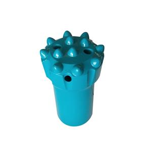
(II) Alloy teeth of down-the-hole drill bits
Carbide teeth are responsible for receiving the high-frequency stress waves of the hammer and transmitting them to the rock surface to participate in the cutting work. The forces during operation are complex, especially the edge alloy teeth, which are prone to bending moment and torque under the action of high-frequency impact force, resulting in broken teeth or broken teeth. Therefore, when designing the drill bit, it is necessary to comprehensively consider the alloy grade, tooth shape and distribution, and reasonably select them according to the hardness of different rocks, geological structures and working conditions.
Tooth shape of alloy teeth
• Conical teeth: The tooth shape is sharp, the contact area with the rock is small during operation, the resistance is small, it is easy to invade the rock, and the excavation speed is fast. However, due to its thin volume, weak bending and torsion resistance, high tooth height after the teeth are fixed, large bending moment during operation, and easy to break. It is suitable for working pressure below 1.6MPa, rock hardness of about Puerto Rico f=14, no crack interlayer and good geological structure. Under this condition, the economic and technical indicators are significant. The parabolic or bullet tooth shape that has appeared in recent years combines the advantages of conical teeth and effectively improves the bending and torsion resistance and service life of alloy teeth.
• Ball teeth: have excellent bending and torsion resistance, excellent performance in impact toughness and strength, full ball crown, increased wear capacity, long service life, widely used in various geological environments with working pressure and rock hardness, especially in high pressure areas above 1.6MPa and complex geological structures (such as interlayers and cracks). The disadvantage is that the contact area with the rock is large, the friction resistance is large, and the excavation speed and work efficiency are affected.
• Wedge teeth: special structure, large wear capacity, high tooth height, fast excavation speed, long service life, and significant economic performance in environments with low working pressure, rock hardness below f=14 and good geological conditions.
Alloy teeth of different shapes have their own application range and characteristics. The appropriate tooth type should be selected through experiments and combined with actual conditions.
▶ Distribution and number of alloy teeth
• Based on the rock breaking mechanism of down-the-hole drill bits, comprehensive consideration of production economy and work reliability, an eccentric asymmetric non-continuous tooth arrangement method is often used. Eccentricity means that the first tooth at the center of the drill head is offset from the center of the drill bit by L, which is generally 2/3 of the diameter d of the center alloy tooth (see Figure 1), so that the alloy tooth performs circular cutting motion around a certain point during operation to ensure that rock removal is fully and effectively performed.

Asymmetric tooth arrangement ensures the stability and reliability of drilling cutting on the basis of eccentricity. Discontinuous tooth arrangement starts from economy. On the premise of ensuring cutting effect, a limited number of alloy teeth are reasonably arranged to make the alloy teeth evenly stressed and completely remove the rock at the bottom of the blasthole. The minimum number of alloy teeth of the side teeth can be calculated and determined by the empirical formula Nmin ≥ k f1 /f2 (Nmin is the minimum number of alloy teeth of the side teeth, f1 is the impact frequency, f2 is the rotation frequency, k is the empirical coefficient, generally 1.2 - 1.3). This formula is the ideal number of teeth to ensure rock removal within one rotation cycle (as shown in Figure 2a). If the number of teeth is too small, the situation will occur (as shown in Figure 2b). The rock that cannot be completely removed in the first impact frequency will not only complete the rock removal task of this impact, but also remove the rock that was not removed in the previous impact frequency under the same feed rate after the second impact frequency. This will cause the instantaneous force on the alloy teeth to increase sharply. When the strength limit of the alloy is exceeded, the alloy teeth will break and the drill bit will be scrapped. Therefore, when designing the actual number of alloy teeth, the empirical coefficient k should be multiplied to eliminate this possibility. That is to say, within one impact frequency, the sum of the arc lengths of the cutting trajectories of each alloy tooth is greater than the circumference of the circle where the alloy tooth is located (as shown in Figure 2c). This can ensure that the rock is completely removed and the force on each tooth can be appropriately reduced to prevent damage caused by excessive instantaneous cutting resistance. However, the more alloy teeth, the better. Too many will increase costs, increase friction resistance, reduce powder discharge space, and affect the powder discharge effect.

The alloy teeth on the top of the drill bit should be arranged as little as possible while ensuring the cutting effect, so that each tooth is evenly stressed and the rock breaking efficiency is improved. When setting the number and position of alloy teeth, it should be ensured that the projections of each tooth in a certain direction are staggered and there is no gap (see Figure 3) to prevent uncut rock from affecting the excavation speed and drill bit life.

(III) Drill bit powder exhaust and blowing system
The powder exhaust and blowing system of the down-the-hole drill bit consists of the drill bit tail hole, the top surface blowing hole, and the top and side powder exhaust grooves (see Figure 4). The top surface blowing hole and the tail hole are spatially staggered. When designing, it is necessary to comprehensively consider factors such as drill bit diameter, working air pressure, air consumption and tail hole diameter to ensure that all elements match. Usually, when the air pressure is constant, the sum of the cross-sectional areas of each blowing hole should be smaller than the cross-sectional area of the tail hole (S1 + S2 +... + Sn ≤ S0, S0 is the cross-sectional area of the drill tail hole, S1, S2, Sn are the cross-sectional areas of each blowing hole). This structure can play a role in gas storage, make up for the energy and pressure loss of the high-pressure airflow in the pipeline, and facilitate powder and slag removal.

The injection angle α of the blowing hole (the angle between the axis of the injection hole and the center axis of the drill bit) generally increases with the increase of the working air pressure. Tests show that the higher the working air pressure, the closer the high-pressure airflow and rock powder move to the rock cutting surface, which is conducive to slag removal. At this time, the injection angle α should be taken as a larger value. If the air pressure is high and the injection angle α is too small, the dust will move on the steel surface of the drill head after being reflected by the bottom of the hole, aggravating the abrasion of the steel body, causing the middle teeth to be exposed and broken, and shortening the life of the drill bit.
The depth of the powder discharge groove needs to be reasonably selected according to factors such as the working air pressure and rock hardness. The higher the working pressure or rock hardness, the smaller the depth of the powder discharge groove can be; otherwise, it will be larger. The depth of the top powder discharge groove should not exceed the depth of the middle tooth pressed into the steel body, and the depth of the side powder discharge groove should not exceed the center line position of the side alloy tooth, so as not to reduce the steel body's ability to resist external forces, cause collapse and tooth loss, and affect the service life of the drill bit.