Mining PDC drill bits: common failure modes and root-cause analysis
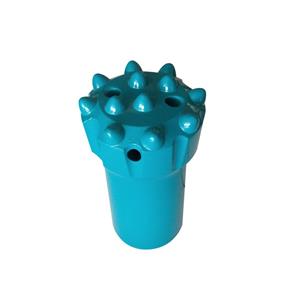
Currently mining PDC bits mainly consist of the bit body, PDC cutting inserts, and gauge-protection alloy. The PDC cutting inserts and gauge-protection alloy are brazed onto the bit body. During normal drilling, the rig transmits torque and feed pressure to the bit through the drill string; the PDC cutting inserts cut the rock at the bottom of the hole, while the gauge-protection alloy shields the bit body circumferentially to prevent rapid wear. During rock cutting the loading on PDC cutters at the bit face is highly complex. Variations in the formation, construction method and equipment selection, operator practice, and bit quality control can all affect performance and lead to different failure modes. Based on field investigations at coal-mine drilling sites, failed mining PDC bits were summarized and analyzed; the following typical failure modes and main causes were identified.

1.1 PDC cutting-insert failures PDC is sintered under high temperature and high pressure. A PDC composite typically comprises a diamond layer and a tungsten‑carbide (WC) substrate.
The principal failure modes of PDC cutting inserts are normal wear, insert loss (pull-out), chipping, and delamination.
(1) Normal wear Normal wear is the expected degradation of PDC cutters during rock cutting. It appears as macroscopic abrasive loss of the diamond layer and the WC substrate; the worn surface shows no distinct fracture or chipping marks.
(2) Insert loss (pull-out) Insert loss occurs when a PDC insert detaches entirely from the bit body, causing bit failure. The characteristic sign is a complete separation of the insert from the bit, with the brazing pocket in the bit body showing no residual alloy.

Main causes of insert loss:
Excessive bottom-hole temperature: when dry drilling is used or the bit’s water passages are blocked, high-speed rotation and cutting generate heat that cannot be removed, causing the bottom-hole temperature to rise sharply. If the temperature exceeds the brazing filler metal’s critical temperature, the brazing melts and the insert falls out.
Poor control of brazing process: inadequate pre-weld cleaning, incomplete or porous brazes, poor degassing, or improper post-braze holding temperature/time can all lead to insert pull-out.
Countermeasures:
Manufacturers must strictly control production processes, especially brazing, to ensure full, sound welds.
On site, adopt wet drilling (sufficient flushing) instead of dry drilling where possible; during deep drilling wait until return flow is established before adding drill pipe; check the bit’s water passages for blockage before running the bit into the hole to avoid localized overheating.
(3) Chipping (edge breakage) Chipping refers to fracture and loss of the PDC diamond layer, often locally; in severe cases the diamond layer may break away together with portions of the WC substrate.
Main causes of chipping:
Cutter material properties: chosen cutters may have low impact resistance or insufficient bond strength between the WC substrate and diamond grit, making them prone to chipping under impact.
Operational parameters: excessive feed pressure/weight on bit (WOB) at the face can overload the cutters beyond their strength limits, causing diamond layer flaking and chipping.
Complex formation: in hard-broken formations impact loads can exceed the cutters’ impact toughness and cause chipping.
Bit design: an inappropriate cutter rake/cutting angle (e.g., too small a cutting angle for hard formations) increases cutter loading and promotes chipping. The rule of thumb is harder formations generally require larger cutting angles.
External obstacles: encountering rock-reinforcement elements such as roof bolts or cable bolts in underground workings can readily cause cutter chipping.
Countermeasures:
Adhere to the bit manufacturer’s recommended operating parameters.
Select and design bits targeted to formation conditions: for hard formations increase cutter rake/cutting angle to reduce aggressiveness and protect cutters; for hard fragmented formations choose PDC cutters with higher impact toughness or alter the cutter external geometry to improve impact resistance (e.g., convexo‑curved faces have better impact performance than flat faces under comparable manufacturing processes).
Plan hole trajectories to avoid known anchors or bolts where possible.
(4) Delamination Delamination denotes separation between the diamond layer and the WC substrate of the PDC composite.
Main cause of delamination: Significant residual stresses between the diamond layer and the WC substrate, combined with the difference in thermal expansion coefficients, lead to mismatched contraction under the alternating heating from friction and cooling by the drilling fluid. The combined effects of impact loading and residual stress can cause the diamond layer to peel from the substrate.
Countermeasures:
During manufacture, select appropriate bonding materials and processing parameters to minimize residual stress between the diamond layer and the WC substrate.
Optimize the substrate–interface geometry (e.g., new interface shapes) to improve mechanical interlock and bonding strength between the diamond layer and the substrate.
1.2 Bit-body failures Bit-body failures mainly present as fracture of the bit wings (bit blades).
Wing fractures occur mostly in sintered/matrix bits and are rare in steel-bodied bits.
Causes of wing fracture in matrix bits:
Impact on the bit wings during make-up or break-out: matrix bit crowns are often produced by powder metallurgy and are sintered in one piece. Compared to standard steel-body bits, sintered matrix bits have higher wear resistance but lower toughness; hitting the bit wings during removal can easily cause wing fracture.
Poor control of the sintering process: incomplete sintering or inclusions (unsintered powder islands) mean the powder did not fully consolidate into a homogeneous matrix.
Countermeasures:
During make-up and break-out, operators should use proper tools (e.g., pipe tongs or spanners) to assist and avoid hammering on the bit wings.
Manufacturers must strictly control sintering quality: tightly control the sintering process and perform periodic checks on metal powder feedstock to ensure it meets process specifications.